Articles/Case Studies
Standards-Based Motor Protection and Condition Monitoring for Electrical Motors
Applying IEEE 493-2007, IEEE 3004.8-2016, and ISO 10816-3:2009 with the ATC Diversified Motor Director™
Electric motors rarely fail without warning. They fail after weeks or months of progressive mechanical stress, thermal degradation, and electrical imbalance that go undetected in most facilities.
Three major standards describe this reality from complementary angles:
- IEEE 493-2007 (Gold Book) — documents why motors fail based on field statistics
- IEEE 3004.8-2016 — defines how motors must be protected in industrial systems
- ISO 10816-3:2009 — defines how vibration must be measured, evaluated, alarmed, and tripped at the bearings where most failures begin
Together, these standards establish a complete philosophy:
Motor reliability depends on monitoring the mechanical, thermal, and electrical precursors to failure, not just reacting to faults.
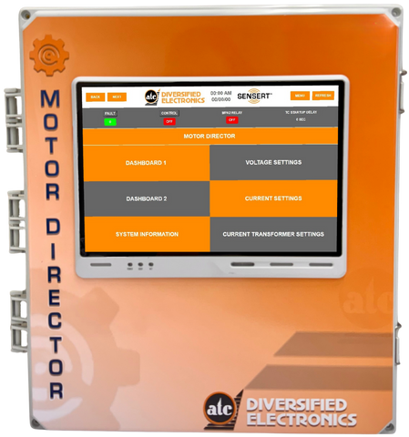
The ATC Diversified Motor Director™ Advanced Motor Protection System provides a practical way to implement this full standards-based philosophy at the MCC, starter, or feeder level, where traditional protection has historically been insufficient.
What Actually Causes Motor Failures
IEEE 493 compiles decades of industrial failure data and consistently shows:
- Bearing failures are the largest contributor to motor outages
- Insulation failures are strongly tied to overheating and voltage stress
- Misalignment, imbalance, and looseness frequently precede failure
- Failures develop gradually, with measurable warning signs long before trip conditions occur
IEEE emphasizes that: Motors rarely fail without warning and the warning signs simply go unmonitored. This shifts the philosophy from: “Trip when a fault happens” to “Detect the conditions that cause faults.”
The Engineering Requirements for Motor Protection
IEEE 3004.8 translates reliability lessons into protection requirements. It requires protection to consider:
- Motor heating characteristics
- Starting stress and locked-rotor heating
- Voltage unbalance and phase loss
- Ground faults and overcurrent
- Power quality issues
- Motor importance to the facility
The standard strongly recommends the use of a multifunction motor protection relay (IEEE Device 11) like the ATC Diversified Motor Director™ Advanced Motor Protection System instead of relying on overload relays and breakers alone, especially for low-voltage (240VAC to 480VAC) MCC motors.
Why Bearings and Vibration Matter
IEEE 493 shows bearings are the dominant failure mode.
- Where do bearing problems show up first? At the bearing housing as increased vibration.
ISO 10816-3 is written specifically for: Industrial rotating machines above 15 kW, including electric motors, measured on the bearing housings in place. It defines:
- Where to measure
- What to measure
- What values mean
- How to set alarms and trips
- How to detect early changes (25% rule)
What ISO 10816 Requires Technicians to Do
ISO requires vibration to be measured:
- On bearing housings
- In two radial directions
- As RMS velocity (mm/s)
- Across 10–1000 Hz
- At normal load and temperature
- Using the highest reading
This removes subjectivity from vibration assessment.
ISO 10816 Severity Zones — Turning Vibration into Action
| ZONE | MEANING | ACTION |
| A | Like new | Record baseline |
| B | Acceptable | Trend |
| C | Unsuitable long term | Plan maintenance |
| D | Risk of damage | Trip |
For typical MCC motors (Group 2, rigid support):
| BOUNDARY | RMS VELOCITY (mm/s) |
| A/B | 1.4 |
| B/C | 2.8 |
| C/D | 4.5 |
These are internationally accepted limits.
The Most Important Rule — The 25% Change
ISO Criterion II states: A change of 25% from the machine’s normal vibration is significant and must be investigated.
This aligns directly with IEEE 493’s finding that failures develop gradually.
Why Combining Electrical, Thermal, and Vibration Is Powerful
Most motor problems affect multiple domains simultaneously:
| PROBLEM | VIBRATION | TEMPERATURE | ELECTRICAL SIGNATURE |
| Misalignment | ↑ | ↑ | Current Imbalance |
| Bearing Wear | ↑ | ↑ | Load Increase |
| Voltage Unbalance | — | ↑ | Current Imbalance |
| Overload | — | ↑ | Current Rise |
| Looseness | ↑ | — | Power Fluctuation |
Seeing all three provides earlier and more accurate diagnosis than any single parameter.
How the ATC Motor Director Is Applied in the Field to Meet These Standards
Step 1 — Electrical Integration (IEEE 3004.8)
Motor Director is connected to all three motor phases and control circuits to monitor:
- Thermal loading
- Phase unbalance
- Overcurrent
- Undervoltage
- Phase loss
- Ground fault awareness
This fulfills the multifunction relay role IEEE 3004.8 recommends.
Step 2 — Thermal and Starting Protection
Motor Director tracks:
- Start duration
- Inrush magnitude
- Restart attempts
- Cumulative heating
This enforces thermal limit curves and locked-rotor protection.
Step 3 — Vibration Sensor Installation (ISO 10816)
A vibration sensor is mounted:
- On the bearing housing (drive end preferred)
- Radially
- Connected to Motor Director
- Configured for RMS velocity (mm/s)
This matches ISO measurement requirements exactly.
Step 4 — Threshold Setup Using ISO Zones
For a Group 2, rigid motor:
- Alarm ≈ 2.0–2.5 mm/s
- Additional 25% change alarm
Step 5 — Establish Baseline (IEEE 493 + ISO)
At normal operation, record:
- Vibration
- Current
- Voltage
- Power Factor
- Temperature
Future alarms are based on deviation from this baseline.
Step 6 — Continuous Monitoring and Trending (IEEE 493)
Motor Director trends all parameters to detect:
- Bearing wear
- Misalignment
- Looseness
- Cooling issues
- Electrical stress
Weeks or months before failure.
Step 7 — Alarm, Notification, and Trip Strategy
- Alarm when entering ISO Zone B trend
- Electrical/thermal alarms per IEEE
From Reactive Protection to Standards-Based Predictive Reliability
| OLD APPROACH | STANDARDS-BASED APPROACH |
| Overload relays only | Multifunction monitoring |
| No vibration visibility | ISO 10816 severity monitoring |
| Fixed setpoints | Baseline +25% |
| Failure-based maintenance | Trend-based maintenance |
Practical Results Facilities Can Expect
Facilities using this approach typically experience:
- 50–80% reduction in unexpected motor failures
- Longer bearing and winding life
- Better root-cause diagnosis
- Lower maintenance costs
- Higher uptime
Because they stop reacting to faults and start detecting causes.
When installed and configured as described, the ATC Diversified Motor Director™ enables facilities to implement all three standards in a practical motor control installation.
Motor protection is no longer about stopping faults; it is about preventing failure using standards-based monitoring.
References
- IEEE 493-2007 — Reliability of Industrial Power Systems
- IEEE 3004.8-2016 — Motor Protection Practice
- ISO 10816-3:2009 — Vibration Severity Evaluation for Industrial Machines
Click here to download the PDF version of this article.
Common Questions About Standards-Based Motor Protection and Condition Monitoring
What is standards-based motor protection?
Standards-based motor protection uses established engineering guidance to monitor the electrical, thermal, and mechanical conditions that can lead to motor failure. Instead of relying only on overload trips, it applies standards such as IEEE 493, IEEE 3004.8, and ISO 10816-3 to support a more complete motor reliability strategy.
Why are IEEE 493, IEEE 3004.8, and ISO 10816-3 important for motor reliability?
These standards address motor reliability from different but connected angles. IEEE 493 documents common causes of industrial motor failure, IEEE 3004.8 outlines motor protection practices, and ISO 10816-3 provides guidance for evaluating vibration severity on industrial rotating machines.
How does Motor Director support a standards-based motor monitoring approach?
Motor Director supports a standards-based approach by monitoring electrical, thermal, and mechanical indicators in one system. It can track phase conditions, current, voltage, thermal loading, operating trends, and vibration data to help maintenance teams identify developing problems before failure occurs.
What does ISO 10816-3 measure for motor vibration?
ISO 10816-3 focuses on vibration measurement for industrial rotating machines, including electric motors above 15 kW. It evaluates vibration at the bearing housing using RMS velocity measurements, helping technicians determine whether vibration levels are acceptable, should be trended, require maintenance, or indicate damage risk.
What is the 25% vibration change rule?
The 25% vibration change rule refers to the idea that a significant increase from a machine’s normal vibration baseline should be investigated. This makes baseline monitoring important because the concern is not only the absolute vibration value, but also how much the machine has changed from its normal operating condition.
Why is baseline monitoring important for electric motors?
Baseline monitoring establishes what normal operation looks like for a specific motor. Once vibration, current, voltage, power factor, and temperature baselines are recorded, future changes can be compared against normal conditions to help identify bearing wear, misalignment, looseness, cooling issues, or electrical stress earlier.
What is the difference between overload protection and condition monitoring?
Overload protection is designed to react when a motor draws excessive current or reaches a defined trip condition. Condition monitoring tracks operating behavior over time, including vibration, temperature, current, voltage, and power quality, so maintenance teams can identify the causes of failure before a trip occurs.
How does combining electrical, thermal, and vibration data improve motor diagnostics?
Many motor problems affect more than one operating condition. Bearing wear may increase vibration and load, voltage unbalance may increase temperature and current imbalance, and misalignment may affect vibration, temperature, and current behavior. Combining these data points helps maintenance teams diagnose motor problems with greater confidence.