PRODUCTS
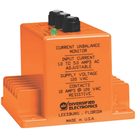
3-Phase Current Unbalance and Over Current Monitor (CLB Series)
The CLB Series is designed to protect three phase equipment againstCURRENT UNBALANCE and OVER CURRENT conditions.The control voltage is continuously applied to supply the sensingcircuitry and the internal relay. When the current of any phase approximately20% above the maximum operating current, the inrush delaybegins. This delay disables the over current sensors while high inrushcurrents are present. Any time the currents are outside the preset limitsafter completion of the inrush delay, the internal relay will de-energize(Drop-out).A 2% differential (hysteresis) between Pick-up and Drop-out is incorporatedto prevent chattering when operated in the automatic reset modeand the current is at the trip point.The reset mode is selected as follows:AUTOMATIC: Place a jumper between pins ten (10) and eleven (11).MANUAL: Place a normally open switch between pins ten (10) andeleven (11). When there is a loss and reapplication of the controlvoltage, the external switch must be closed before the circuit will againbecome operative. An External CT may be used to extend the range of the Current Monitor.
Find Your Part Number
Not sure? Call for help. Phone: 304-387-1200
| Part Number | Description |
|---|

